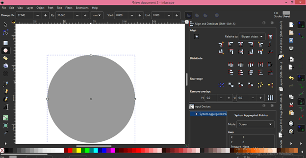

Inkscape has a habit of not connecting the first and last points on a path if there is a straight line between them. The first step to a successful export is checking the paths produced by inkscape are complete. (Some of these issues likely come from inkscape’s native format being SVG, which is more flexible and tolerant than DXF - SVG is a display format, DXF an engineering format). Unfortunately, the DXF format is much, much more versatile than OpenSCAD’s parser. In this step, we’ll be exporting the traced image to a DXF file, the format that OpenSCAD is capable of importing. Now is a good time to make any edits to the vector graphic you want to make - for example, touching up lines that didn’t trace properly.
#3d vector inkscape update#
Press update to make sure the graphic still looks acceptable to you, then OK to accept. You’ll need to make sure the image is still selected.

The best way to do this is to ask inkscape to trace it. Next, we need to convert this to a vector graphic. I’ve borrowed the ACM’s logo for this process.įirst step: get it into inkscape. Otherwise, its just a standard 2D to 3D extrusion. The last step is documented solely because there are a number of little details which can totally stop this process from working if you don’t get them exactly correct.

Next, in a part studio tab, create a sketch and choose the Insert DXF or DWG tool. To load the design in Onshape, begin by choosing Import from the tab menu in the lower left and select your DXF: In the save dialog, be sure to choose the dxf file type: Both are parametric, permitting subsequent revision without restarting from scratch. The other uses OpenSCAD for a more programmatic approach. One uses Onshape for an interactive approach. Here are two ways to give your paths some depth. So, you have some vector artwork in Inkscape and you want to make it into a stamp or some other sort of 3D-printable gewgaw.

Making Extruded 3D Models of Inkscape Illustrations


 0 kommentar(er)
